Introduction to this series is
here.
Phase 1 is initiated. I will adhere to a keep-it-simple approach during development. So setting up the window went very quickly; no config files, no nothing.
The first step was to create the nodes in a spherical arrangement. I divided the space into unit cubes and looped through them. Where the innermost and outermost vertices of the cube was on opposite sides of the surface, I placed a node.
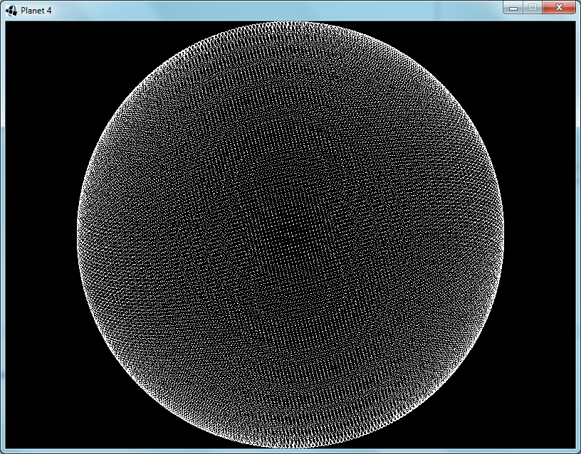
Each node represents a surface of about 128m×128m. Since they're neither square nor uniform the area differs from node to node. I experimented with different sized planets a bit and decided that radius 60 makes a medium-sized planet. The circumference is about 48km, which is definitely much further than I have ever traveled in Minecraft. What's the point of an infinite world, then?
 |
| Fig. 1: Radius 60 Sphere - Each node represents a 128m×128m area |
Next I move the nodes so that they are no longer on the sphere, but rather arranged in a grid. This will make noticing and understanding bugs much easier.
 |
| Fig. 2: Nodes are now aligned to a grid for debugging visualization |
I reduce the size of the planet to radius 5, implement an algorithm for finding their nearest neighbours and link them up. Ideally, I would have used
Delaunay triangulation, but I decided to keep it simple instead; I have never done Delaunay triangulation before. So I looped through the nodes and checked adjacent grid points for neighbours to link to. The first time I only checked in the positive directions. Figure 3 shows the inadequacy of this optimization:
 |
| Fig. 3: Added node-to-node links - My first bug is apparent |
A simple fix is to just check the negative directions as well. This does slow it down a bit though. There is a faster way, but it is complicated, so I stuck to the simple way.
 |
| Fig. 4: Fixed the links bug |
While my current algorithm
does find every node that will contain a part of the sphere's surface, this causes some foreseeable problems, in that the double layer in some regions will stop the erosion algorithm from working correctly. I take a cross section to see what it looks like (Fig.5) and see two possible solutions. I could get rid of all diagonal links, or I could remove the extra layer before linking up the nodes.
 |
| Fig. 5: Cross section shows double layering |
I decided to implement the node removal method, since this will simplify the eventual creation of the zones. Each node that has three axis-aligned neighbours that are closer to the center is removed. The cross section looks okay, so I switch back to the full sphere view:
 |
| Fig. 6: Removing the extra layer is not working as intended |
That's no sphere! I tried a few different techniques, with no positive results. Eventually I realize the problem: When I remove a node I change the circumstances of the surrounding nodes. Near the axis-aligned planes that pass through the sphere's origin this causes that some nodes will no longer be removed. The solution is to keep a set of nodes that need to be removed, and only remove them after all have been found.
 |
| Fig. 7: It works now |
And finally I put the nodes back into their original spherical arrangement.
 |
| Fig. 8: Off the grid and back to a sphere |